Rj22 Rj45 Wiring Diagram

Rj45 Pinout Showmecables Com
Easy Rj45 Wiring With Rj45 Pinout Diagram Steps And Video

Cat 6 Network Cable Diagram Reading Industrial Wiring Diagrams

Rj45 Pinout Amp Wiring Diagrams For Cat5e Or Cat6 Cable Dengan

Rj45 Wiring Diagram Met Afbeeldingen Elektriciteit

Rj45 Pinout Ethernet Wiring Electrical Circuit Diagram
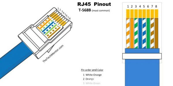
Remember the rj45 wiring order.
Rj22 rj45 wiring diagram. Figure 2 is the wiring scheme for the plug side of an rj 45 connector in accordance with t 568b standards. The typical rj 11 connector has six terminals. This article shows how to wire an ethernet jack rj45 wiring diagram for a home network with color code cable instructions and photos and the difference between each type of cabling crossover straight through ethernet is a computer network technology standard for lan local area network. 5 not used 6 rtn signal return common reference for logical signals.
Alternate designations omit the letters while separating the position and contact quantities with either an x 6x2 or. It was introduced commercially in 1989 and became ieee standard 802 3 in 1983. The diagram is shown with the hook clip on the underside. We hope you enjoyed it and if you want to download the pictures in high quality simply right click the image and choose save as.
The wiring diagram is shown with the hook clip on the underside. Rj45 connectors pin. Figure 1 is the wiring scheme for the plug side of an rj 11 connector. Collection of cat 6 wiring diagram rj45.
Rj12 wiring diagram rj12 pinout colors wiring diagrams techwomen co regarding rj12 to rj45 wiring diagram image size 600 x 240 px and to view image details please click the image. 3 r remote off required or remote off control 4 tr data line required for rs485 communication. The wall jack may be wired in a different sequence because the wires may be crossed inside the jack. Click to find view print and more.
A wiring diagram is a streamlined standard photographic depiction of an electric circuit. The complete ethernet pinout cable wiring reference with wiring step by step guide. Here we have another image t1 rj45 wiring diagram data wiring diagram schematic rj45 wiring diagram featured under rj45 to rj12 cat3 wiring diagram wiring schematics diagram rj45 wiring diagram. Here is a picture gallery about rj12 to rj45 wiring diagram complete with the description of the image please find the image you need.
Modular connectors are designated using two numbers that represent the maximum number of contact positions and the number of installed contacts with each number followed by p and c respectively for example 6p2c is a connector having six positions and two installed contacts. Appendix a pin out of rj12 rj45 connectors rj12 connectors pin signal name description 1 not used 2 tr data line required for rs485 communication. Rj45 pinout diagram shows wiring for standard t568b t568a and crossover cable. It reveals the components of the circuit as simplified shapes and the power as well as signal connections in between the devices.

Rj45 Ethernet Cable Wiring Diagram With Images Ethernet Cable

Straight Through Cable Color Code Wiring Diagram A Color Coding

Rj45 Wiring Diagram Avec Images Schema Electrique Schema

Rj45 Wiring Diagram For Ethernet Ethernet Wiring Rj45

Cat6 To Rj11 Wiring Diagram With Images Wire Installation

Nowdays Ethernet Is A Most Common Networking Standard For Lan

Paths Fiber Optics Cat5e Cat6 Plenum Rated Cable Lock Assembly

Rj11 To Rj45 Wiring Diagram Dolgular Phone Cables Electronic

Tia Eia 568a Ethernet Rj45 Plug Wiring Diagram At Cat6 Cable

Splitter Wiring Diagram For Rj 45 100base Tx Uses 2 Pairs There

Rj11 To Rj45 Wiring Diagram With Images Usb Cable Wire

Rz 7629 4p4c Connector Wiring Diagram Wiring Diagram

Image Result For Rj45 Wiring Diagram Tattoo Med Billeder
